Your design is exceeding the radiated emissions allowed by EMC regulations, now what? Whether you’re performing pre-compliance testing or troubleshooting a failed formal compliance test, our latest generation oscilloscopes make what was once an overwhelming task far simpler and more straightforward. Below are two helpful tips and a case study to help you troubleshoot EMI. For an even deeper dive into the subject, check out our app note here.
Using Synchronized Time and Frequency Domain Analysis
Examining the coincidence of EMI problems with electrical events is arguably the most time-consuming process in EMI diagnostics. In the past it was very difficult to correlate information from spectrum analyzers and oscilloscopes in a meaningful way. But with Spectrum View on Tek’s 4, 5, and 6 Series Mixed Signal Oscilloscopes, solving RF measurement challenges has become a much simpler process.

Figure 1. Spectrum View lets you view time, frequency and amplitude on the same screen with measurement data uniquely available for each domain.
Made possible by next-generation ASIC technology, Spectrum View:
- Enables the use of familiar spectrum analysis controls like center frequency, span, and RBW on an MSO
- Allows optimization of both time and frequency domain displays independently
- Improves the update rate of the spectrum display
- Improves achievable frequency resolution in the frequency domain
- Enables a signal to be viewed in both a waveform view and spectrum view without splitting the signal path
- Allows easy and accurate correlation of time domain events and frequency domain events
For more information on how to optimize various debugging scenarios on MSOs with Spectrum View, check out our technical brief here.
Using Near-field Probes
Near field probes are essentially antennas which are designed to pick up the magnetic field (H-field) or electric field (E-field) variations. In general, near field probes do not come with calibration data because their response is highly dependent upon the distance and orientation of the probe to the UUT and the signal source, so they are intended for making relative measurements.


Figure 2. Position an H-field probe in line with current flow so magnetic field lines pass through the loop.
H-field probes have a distinctive loop design and should be held with the plane of the loop in-line with the current flow, such that the loop intersects the magnetic field lines of flux. As such, when searching for emissions, the probe is often held with the plane of the loop parallel to the circuit board surface. The size of the loop determines both the sensitivity and the area of measurement, so it’s important to take care when using these types of probes to isolate a source of energy. Near field probe kits will often include a number of different sizes so that you can use a progressively smaller loop size in order to narrow the area of measurement.
H-field probes are very good at identifying sources with relatively high current such as:
- Low-impedance nodes and circuits
- Transmission lines
- Power supplies
- Terminated wires and cables

Figure 3. Position an E-field probe perpendicular to conductors to observe electric fields.
E-field probes function as small monopole antennas, and respond to the electric field, or voltage changes. When using these types of probes, it is important to keep the probe perpendicular to the plane of measurement. In practice E-field probes are ideally suited for zeroing in on a very small area, identifying sources with relatively high voltages as well as sources with no termination such as:
- High-impedance nodes and circuits
- Unterminated PCB traces
- Cables
Case Study
This case study will illustrate the process of gathering evidence to isolate an EMI source. An EMI scan of a small microcontroller system indicated an over-limit failure from what appears to be a broadband signal centered around 140 MHz.
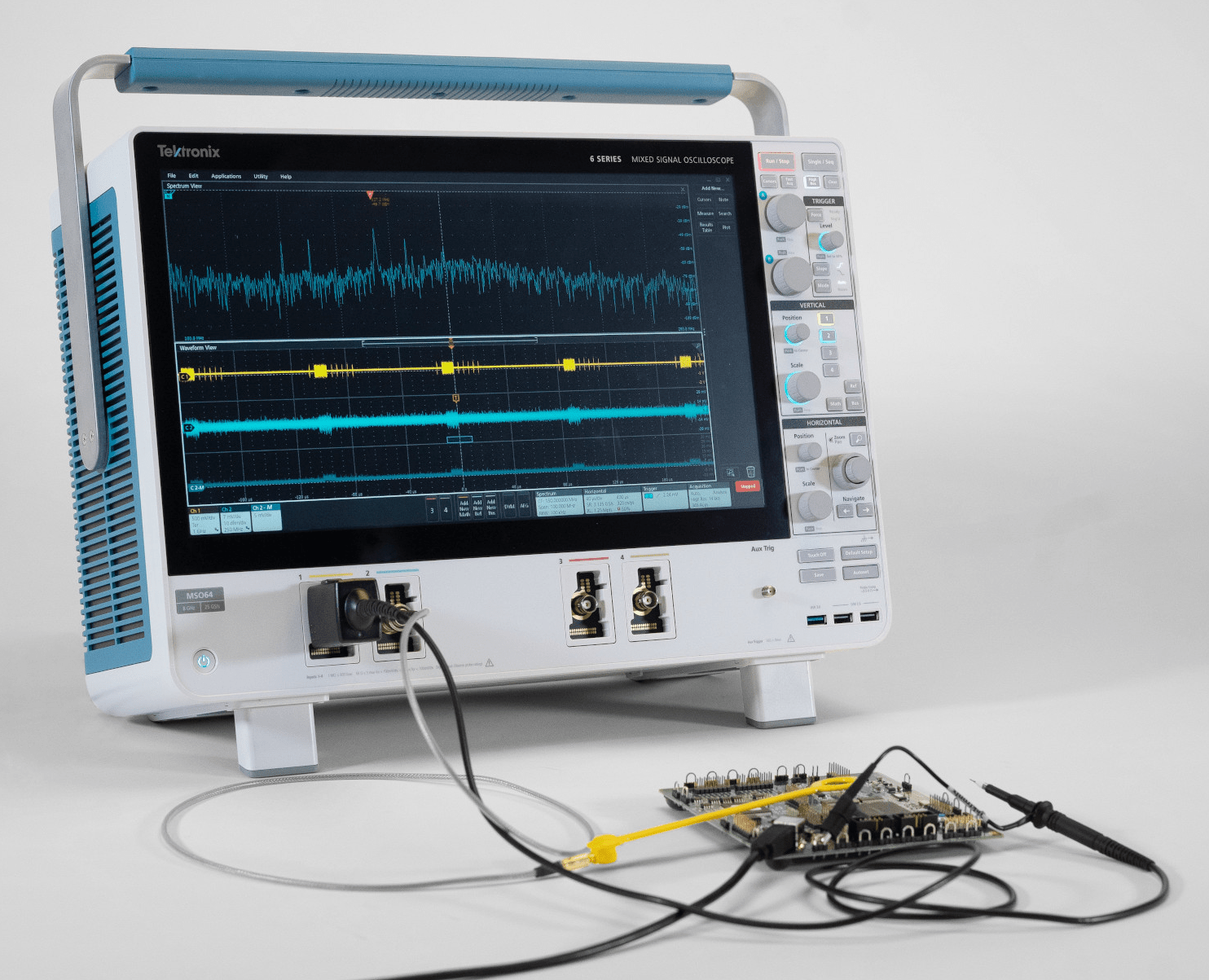
Using Spectrum View on a 6 Series MSO (Figure 4), an H-field probe is connected to the RF input so that we can localize the source of the energy.

Figure 4. Test setup combines analog oscilloscope channels and spectrum analyzer channel on a mixed domain oscilloscope.
It’s important to orient the H-field probe so that the plane of the loop is in-line with the conductor being evaluated, thus positioning the loop so that magnetic field lines of flux pass through it. Moving the H-Field probe around the PCB, we can localize the source of energy. By selecting a narrower aperture probe we can focus the search in a smaller area.
Once a potential source of energy is located, the RF Amplitude vs. Time trace (Figure 5) may be used to gather more information. By using a voltage probe and browsing electrical signals in the area, you can look for coincidence between the RF emissions and time domain signals.

Figure 5. Probing signals with a passive probe on Channel 1 (yellow) uncovers a signal that correlates with the RF.
This bottom shows the integrated power vs. time for all signals in the span. In Figure 5 we can clearly see a large repetitive pulse. Moving the spectrum time through the record length of the acquisition, it’s now possible to see that the EMI event (i.e. the wideband signal centered around 140 MHz) directly corresponds to the large pulse. Browsing around with a 10X voltage probe (the yellow trace) we find bursts of data that correlate well with the RF bursts, pointing to a relationship between the signal and the emissions.
If you want an even deeper dive into EMI troubleshooting with an oscilloscope and haven’t yet checked out our new application note “EMI Troubleshooting with the Latest-Generation Oscilloscopes” you can download it here.